
As soon as I finished my Horizontal Travel Robot Arm prototype and was able to reliable make pick and place motions using simple X, Y, Z inputs, I decided to build a real use case that could show it’s potential for real world applications.
Enabling the robot to have Computer Vision seems like a very straightforward case, and I learned a lot that I want to share, as most likely you will find it useful.
Just in case you want to dive right in, you can access the code via my Github HTA0 robot project.
Note: I’ve taken the liberty of highlighting what I consider the most important parts. I’m counting you will refer to the code repository as well as the multiple diagrams I reference below.
Coordinates and Frames of Reference
You can read through my Medium post on the overview of the robot and watch the video of it in operation in Youtube.
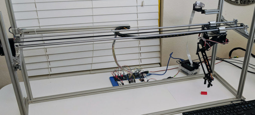
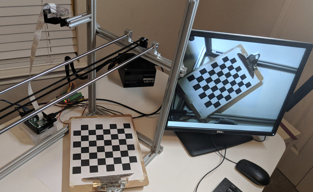
As a reminder, this is the setup of this robot:
As I dive deeper in this blog, it will be very important to keep in mind the frames of references I’ve used:
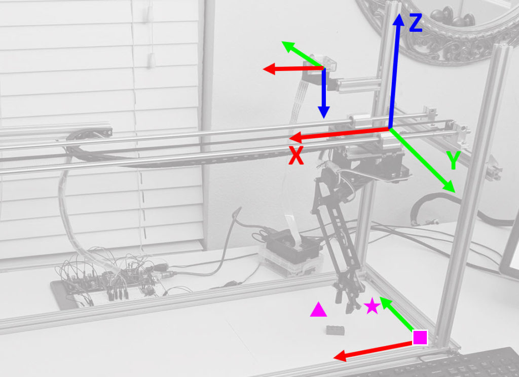
Red is the X-axis, Green the Y-Axis and Blue the Z-axis, the arrows point in the direction of Positive increases. This illustration will be crucial to understand the code and how you can use it on your own projects (which may have different frames of reference based on your application).
OpenCV Camera Calibration and 3D Reconstruction
Formulas
The main reference I have used for this, is the OpenCV 2.4 and 3.0 documentation, using these three pages:
- Calibration Tutorial
- Camera Calibration and 3D Reconstruction
- Documentation for Camera and 3D libraries
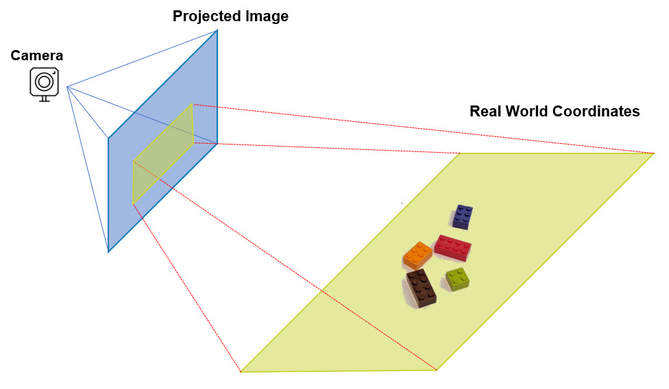
Following the steps to Calibrate the camera were really straight-forward, but the challenge for me in this journey was how to calculate real-world X Y Z coordinates from a given Image’s projection points. I was looking for this, and I couldn’t find any references that could easily explain how to do it:
The main challenge I found with this pinhole model, is that if you want to solve for X Y Z, it cannot be done, because you cannot calculate the inverse of the R|t matrix as it is not square.
Before I dive into the solution, it is important to understand the pinhole camera model and coordinates:
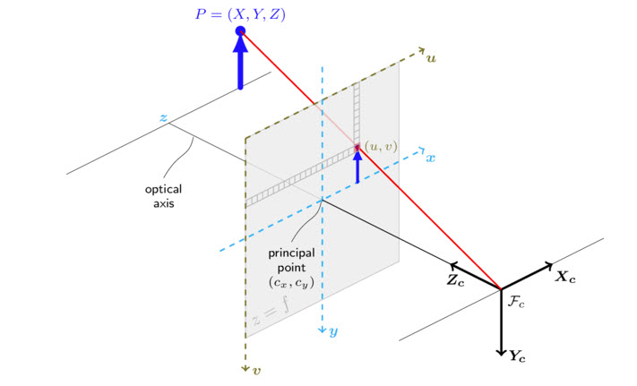
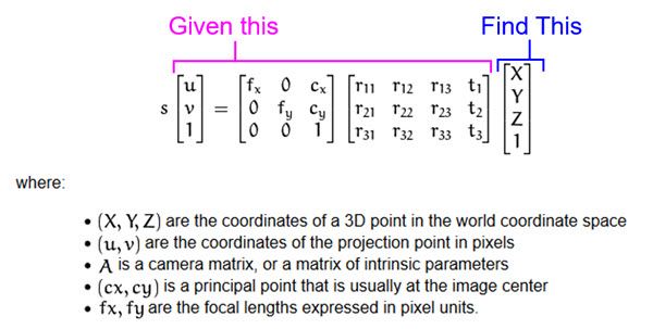
And this is important, because if your setup has a z value that is not equal to zero, the pinhole camera model simplifies to:
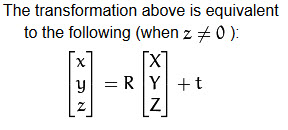
To make it work, I added the scaling factor and camera matrix, to arrive at u, v which now enabled to solve for X Y Z in the following manner:
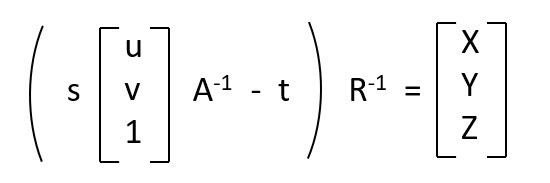
This was a crucial step that enable me to get to a working solution and while working through this another interesting aspect popped-up.
Getting Intrinsic Camera Calibration Right
The first step to calibrate your setup, is to find what is called the intrinsic parameters of your camera, which are based on how the camera is build and one of the key factors to calibrate, is the distortion that is caused by the curvature of the camera lens.
I followed the steps from the OpenCV Camera Calibration and even used a lot of the example code, but I did find something interesting.
Following the Chessboard calibration example, I believe the recommendation is to use 10 or more images and it provides no clarification on how to “pose” the chessboard.
I used the “Undistort” preview to check my work and I found that the undistortion pattern had a lot of variation as follows:
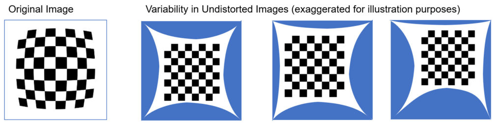
I ended up using around 40 images for calibration and learned that in order to improve the “stability” of the scaling factor (s) I need to position the chessboard in the same plane as where I wanted the detection of X Y Z.
You can find the Python script for this Initial calibration here.
Getting the Perspective Calibration Right
In my setup, I’m using a single fixed camera, which means that once we calibrate for the perspective, the model should begin to work. To get to this point, It involved a series of more steps to get it to work reliably, which I will explain.
The first step, is to identify the Cx , Cy and z values for the camera, and we use the New Camera Matrix to find that Cx=628 and Cy=342. If you refer to the pinhole model, these are equivalent to u and v pixel values.
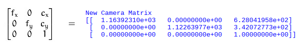
We then manually try to locate the pixel point u=628 and v=342:
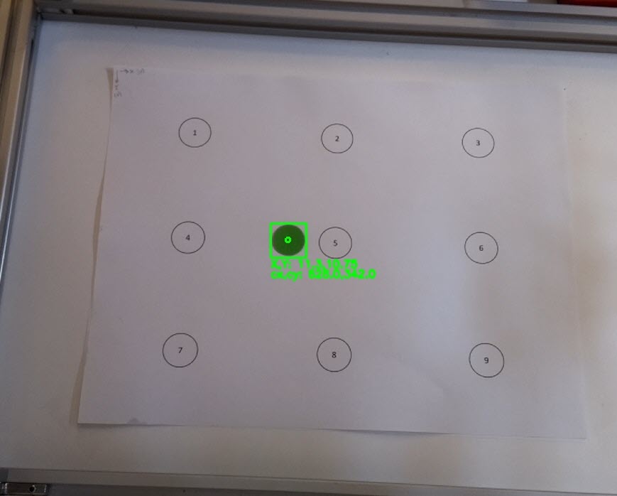
And we measure with a string the z value:
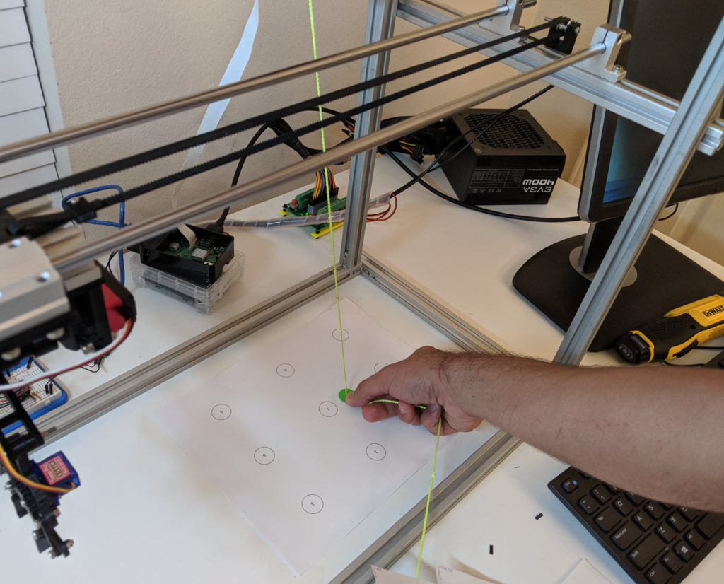
We repeat this measurement for every point, but remember, z is only true for the center point, and we measure the rest of the points as d* (which we have to then us x,y and trigonometry to figure out the z value, which we do automatically in the code). Our sheet looks like this:
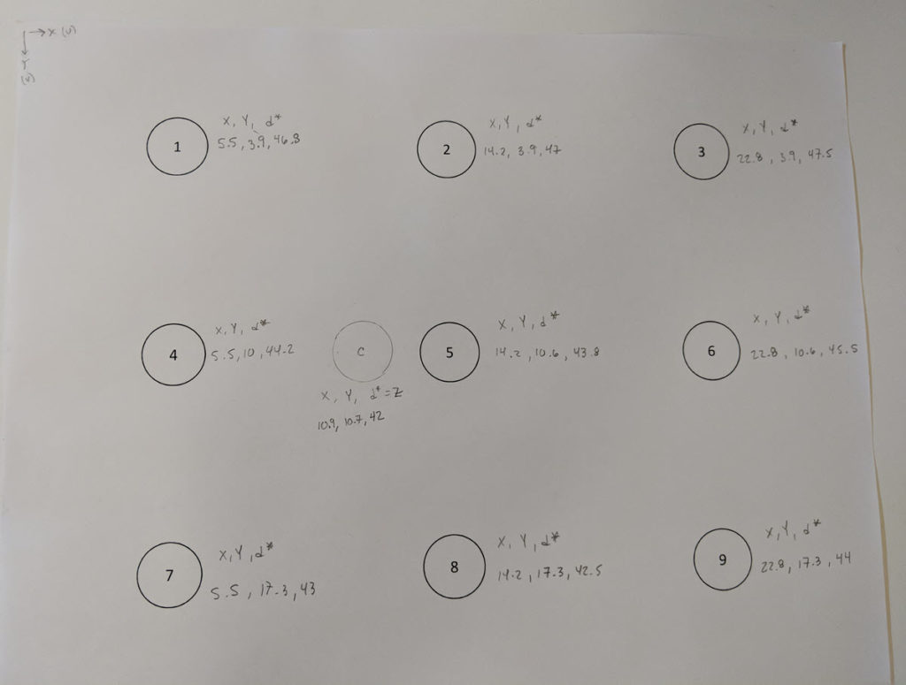
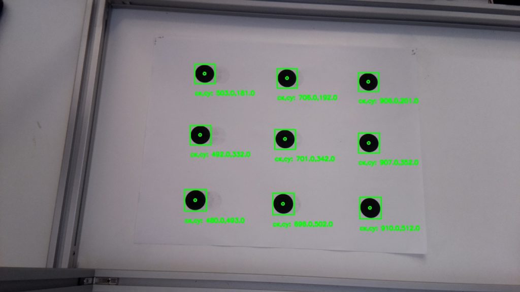
We then use the 9 circle template I created to calculate the Image points, which is the information we need for the perspective calculation.
And we input this manually into the perspective calibration:
#ENTER (X,Y,d*)
#d* is the distance from your point to the camera lens. (d* = Z for the camera center)
X_center=10.9
Y_center=10.7
Z_center=43.4
worldPoints=np.array([[X_center,Y_center,Z_center],
[5.5,3.9,46.8],
[14.2,3.9,47.0],
[22.8,3.9,47.4],
[5.5,10.6,44.2],
[14.2,10.6,43.8],
[22.8,10.6,44.8],
[5.5,17.3,43],
[14.2,17.3,42.5],
[22.8,17.3,44.4]], dtype=np.float32)
#[u,v] center + 9 Image points
imagePoints=np.array([[cx,cy],
[502,185],
[700,197],
[894,208],
[491,331],
[695,342],
[896,353],
[478,487],
[691,497],
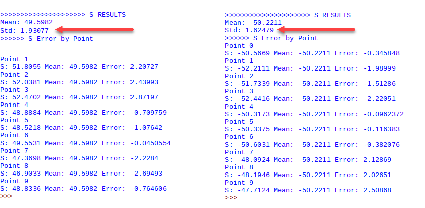
[900,508]], dtype=np.float32)And after running the Perspective calibration, it is important to check the scaling factor s. This is a crucial step, given that your Intrinsic Camera Calibration results drive a lot of variablity in the reliability of the X Y Z calculation, and you should look to iterate and get the scaling factor error as small as possible.
I also found out that the scaling factor (s) varies its signs dependent on the number of points and d* vs. Z calculations, and my hypothesis is this is base primarily on how the frames of reference for the plane vs. camera are different, which makes it change signs during computation.
You can find the Python script for this process here.
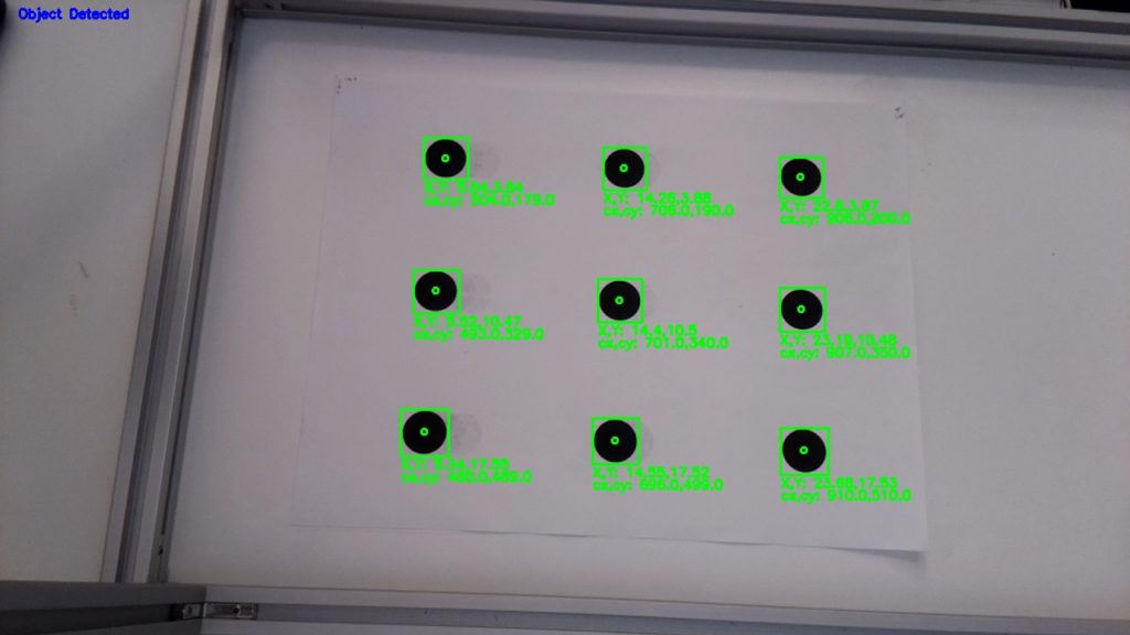
Run-time Calculation of Real World X Y Z from Image Coordinates
Once you have a reliable validation of the predictions on your perspective calibration between world points and image points, I created two files:
- Image Recognition (which I will explain in a separate blog, but in the meantime, here is a simplified explanation)
- Real World XYZ calculation (which takes as input the u, v points captured by Image Recognition)
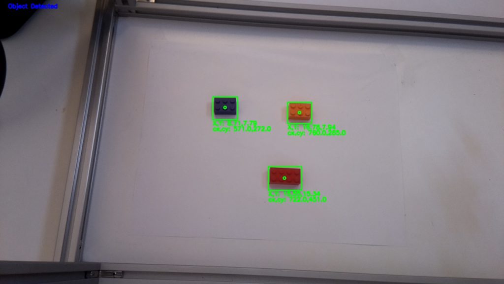
The Image Recognition process performs a background extraction to identify the object, and captures the u, v coodinates from its center (pixel coordinates from the image detect).
The Real World XYZ process, then loads all the Initial Calibrations we did, and calculates the X Y Z points, with the “magic” happening in this specific function:
def calculate_XYZ(self,u,v):

        #Solve: From Image Pixels, find World Points

        uv_1=np.array([[u,v,1]], dtype=np.float32)
        uv_1=uv_1.T
        suv_1=self.scalingfactor*uv_1
        xyz_c=self.inverse_newcam_mtx.dot(suv_1)
        xyz_c=xyz_c-self.tvec1
        XYZ=self.inverse_R_mtx.dot(xyz_c)

return XYZ
Once this is operational, you can then take the time to validate your results, which can be as follows:
Great practice!
Can you explain more detail about perspective calibration?
Hi
Please could you precise how you measure real world coordinates ?
Best regards,
Richard
Nice article! A little glitch is that in the formula above “solving for Real World X Y Z coordinates”, the A^{-1} and R^{-1} should be placed at the left hand side to respect the matrix multiplication rule. Besides that, the theory part is clear and intuitive.
Came here just to say that :)) Matrix multiplication is not commutative!
However, the code from “Run-time Calculation of Real World X Y Z from Image Coordinates” is correct.
yep, and in the camera_realworldxyz.py actually did just as you pointed out
Hi, thank you so much for your work !
Wich camera are you using?
Can I use any web cam ??
Other recommendations ?
Great Project !!!!!!
Hi I want To know from where u find x_Center = 10.9, i got the cx, cy but how to find these Centers ???
X_center=10.9
Y_center=10.7
Z_center=43.4
worldPoints=np.array([[X_center,Y_center,Z_center],
[5.5,3.9,46.8],
[14.2,3.9,47.0],
[22.8,3.9,47.4],
[5.5,10.6,44.2],
[14.2,10.6,43.8],
[22.8,10.6,44.8],
[5.5,17.3,43],
[14.2,17.3,42.5],
[22.8,17.3,44.4]], dtype=np.float32)
It seems that coordinates start from top-left paper corner to each black dot center in centimeters
I have the same question
Hey, have you solved this issue?
I guess you made sg wrong. When you calibrate the camera you estimate the intrinsic params AND the distortion params as well. That is OK.
But when you compute 3D world coordinates, unfortunately dont use the inverse of undistortion in your equations (which are wrongly formed anyway).
This will work only if camera distortion is very little, otherwise computing 3D coordinates (without considering distortion params) and reprojecting to screen (with distortion params) will result in different point coords.
L.
What do the “-t” and “R^-1” represent?
How was the pinhole camera equation simplified when z is not equal to 0?
I am new in Image processing and i need help .PyroCam mounted on the Robot Arm . How can i know moving camera (X,Y,Z) Position ?
later i need to do Perspective Correction of each and every image in real time and for that i am using Top view Transformation model .
Pyro cam takes Thermal images so i cant see any object in the Image .
Thank in Advance for any kind of Help .
Is it necessary to do the perspective calibration. Can please explain it in detail
Hey,Can you tell me if using this method over kinect would be time saver or not?
[…] Calculate X, Y, Z Real World Coordinates from Image Coordinates using OpenCV […]
Hello, is it possible to get in touch with you about this project? I am struggling with finding the real world and X Y Z coordinates manually in the initial perspective calibration step.
Regards,
Zainab Shah Khan
zainabshahkhan13@gmail.com
Great Project !!!!!!
Hi I want To know from where u find x_Center = 10.9, i got the cx, cy but how to find these Centers ???
X_center=10.9
Y_center=10.7
Z_center=43.4
worldPoints=np.array([[X_center,Y_center,Z_center],
[5.5,3.9,46.8],
[14.2,3.9,47.0],
[22.8,3.9,47.4],
[5.5,10.6,44.2],
[14.2,10.6,43.8],
[22.8,10.6,44.8],
[5.5,17.3,43],
[14.2,17.3,42.5],
[22.8,17.3,44.4]], dtype=np.float32)
can i know how you manually try to locate the pixel point u=628 and v=342 from the image?
[…] think I found the answer: Following this post, I introduced a scale factor s for the signed distance, to convert the distance into a real world […]
Dear sir. I’m Yaakob, a student from Malauysia. I am trying to understand your code. Can you help to explain, how did you get the values for d*? For the centre, measure directly from the camera to the centre, but for the rest of the points, how should we get the d* values? So that we can manually insert inside the code. Thank you very much
[…] think I found the answer: Following this post, I introduced a scale factor s for the signed distance, to convert the distance into a real world […]
Which step would be changing if my frames do not match with yours?
Can you give me an e mail to ask some questions please?
In the step of ‘Getting the Perspective Calibration Right’ how did you measure X and Y at u=628 and v=342? similarly how did you find X y at other circle points?
Did you measure it from the corner of the sheet? if yes then why?