
I aimed to built the simplest robot that could prove to be useful in light use cases and my design has two rotating axis that control the Y and Z position, and a linear axis that controls the X position.
For movements, in it’s crudest form the robot arm requires 2 angle inputs (for the servo motors) and number of steps and direction. The X-axis motion is extremely straightforward and can be easily be identified by reading the code, so I won’t cover it in this blog. I will focus on the Y, Z motion.
It is very counter-intuitive to provide angles as inputs and it makes it extremely hard to control the robot. The goals is to provide the robot with a set of coordinates, like Y=5 and Z=-6 and have the program itself figure out the position required by the servos. In the industry this is commonly known as Inverse Kinematics, and the case I’ll describe here, is probably one of the simplest one can find.
You can dive right into the Arduino sketch code in my Github repository.
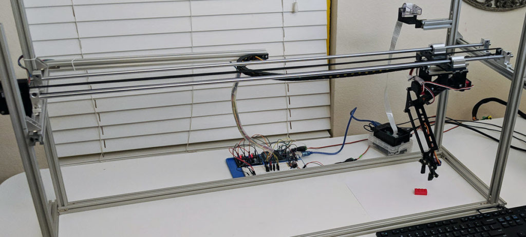
The Robot Arm
You can read through my Medium post on the overview of the robot and watch the video of it in operation in Youtube.
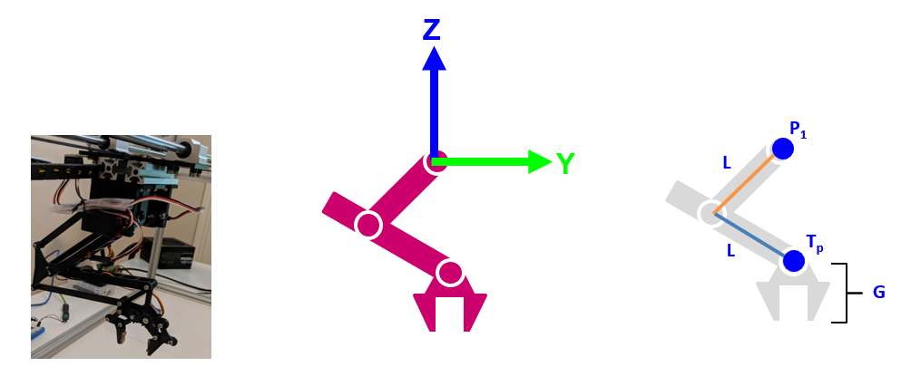
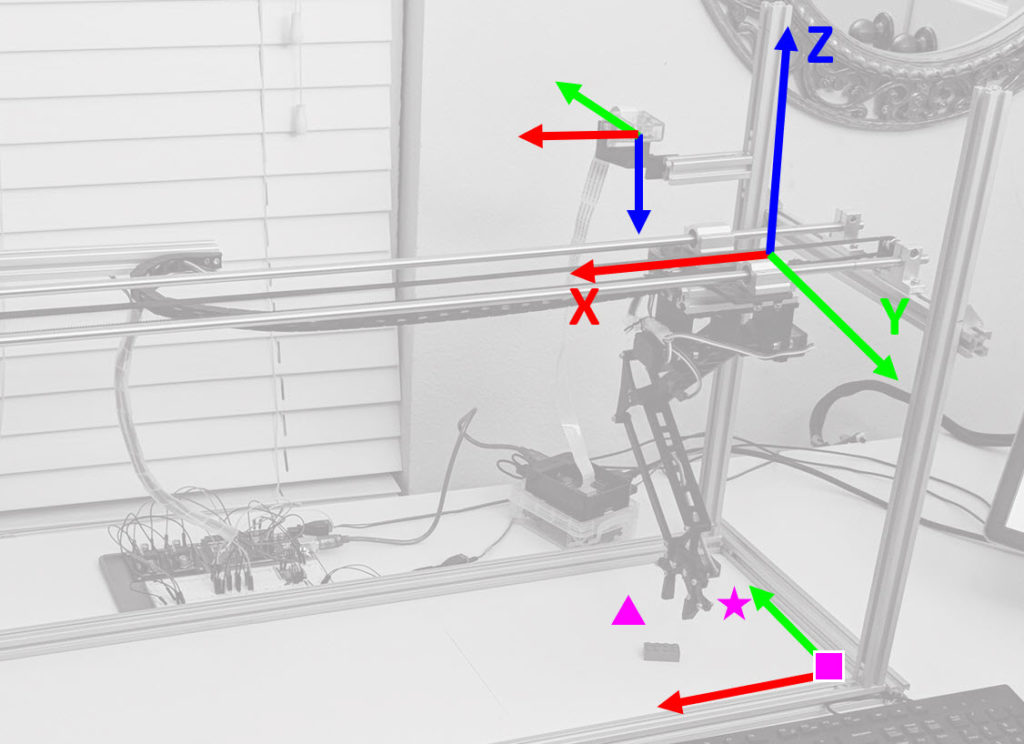
As a reminder, this is the setup of this robot:
Establishing the Frame of Reference
To adequately understand the progression I will go through, it is important to understand th frames of reference of each component. In this blog, we are going to focus solely on the Robot Arm:
For illustration purposes, this is how I will reference the arm in the lines and dots of the rightmost illustration. Our main focus is P1 (point 1) and Tp (Target Point), and we will ignore G, which is the added Z dimension by the Gripper, which is a constant and very easy to add.
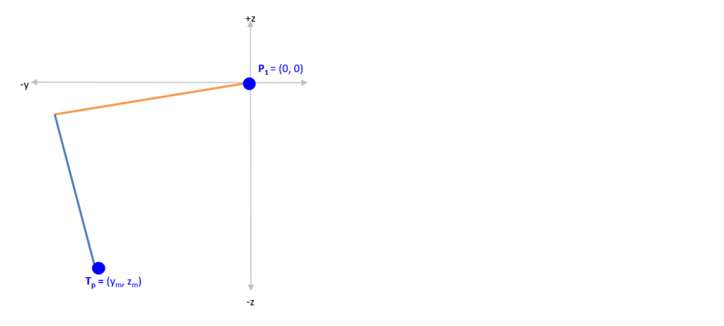
Calculating Servo Angles from Coordinate Inputs
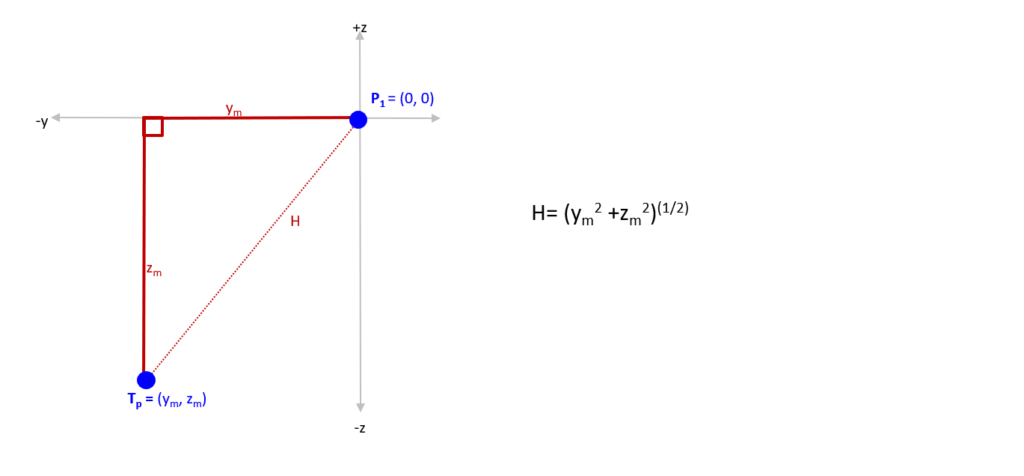
The first step, is mapping out in the coordinate system the two points of interest. P1 is at the base of the robot and it is in the axis of the upper arm (in orange). Tp is our Target Point (where we want the arm to move) and we are looking to be able to provide Ym and Zm to the robot so it automatically figures out the servo angles:
The second step, is realizing that initially we don’t care about the arms, we care about finding H, or the straight-line between P1 and Tp. You can see how we have now converted the problem into a triangle:
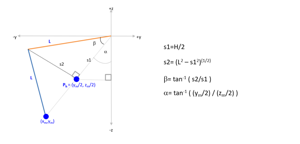
On the third step, we now get both arms back in the picture, which have length L (they are both the same length in this robot). Using trigonometry, we can figure out s1 and s2, which in turn, enables us to figure out angles alpha and beta.
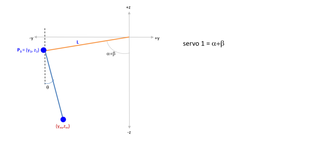
Step four: we now know the angle for servo 1! To figure out the angle for servo 2, we need to identify P3 (point 3).
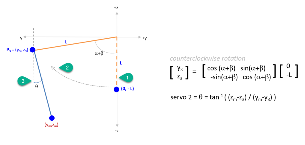
In step five, we place the top arm right on the Z axis (bubble 1) and by performing a rotation by alpha+beta (bubble 3), we get the coordinates of P3. We now have P3 and our original target coordiantes Ym,Zm, and we can calculate the angle for Servo 2!
Note: This is a very simple explanation of how to calculate the arm servos, and they work really work in the range of 0 to 90 degrees. For solutions that require solving beyond this range of angles, several adjustments have to be made to account for the changes in trigonometry.
The Arduino Code
You can dive right into the Arduino sketch code in my Github repository.
The key function I use to perform this calculation is here, and you can see the logic I apply when the servo 2 angle exceeds 90 degrees, to correct for the change in the tangent calculation.
void get_angles_from_yz(double y, double z) {

  //refer to trigonometry illustration for variable description

  double H, s1, s2, aB, aA, aQ, servo1angle, servo2angle, y2, z2, y3, z3;

  //arm length in cm
  int L = 13;

  H= sqrt (pow(y,2) + pow(z,2));
  s1=H/2;
  s2=sqrt (pow(L,2) - pow(s1,2));

  aB=atan(s2/s1);
  y2=y/2;
  z2=z/2;
  aA=atan(y2/z2);

  servo1angle=aA+aB;
  servo1angle= (servo1angle/ (2 * M_PI)) * 360;

  //matrix multiplication - counterclockwise rotation
  y3 = -L*sin(aA+aB);
  z3 = -L* cos(aA+aB);

  servo2angle=atan((y-y3)/(z-z3));

  servo2angle= (servo2angle / (2 * M_PI)) * 360;
  //tangent calculation changes when servo2 exceeds 90 degrees, correction below
  if ((z-z3)>0) {
    servo2angle=servo2angle-180;
  }

  //Absolute Top Arm Angle
  //Top Arm moves 0 to +90
  angle_next[0] = servo1angle;

  //Absolute Middle Arm Angle
  //Midle Arm moves 0 to +90
  angle_next[1] = -servo2angle;

  //Convert to SERVO Angle
  //in this case, a 90 servo position is equal to 71 degrees for Top arm
  //90 servo position is equal to 65 Middle Arm
  angle_next[0] = angle_next[0] + calibrate_TopArm;
  angle_next[1] = angle_next[1] + calibrate_MiddleArm;

}
Movement Trajectory
After the above steps, now you can input coordinates and your robot will reach the destination reliable, but you will quickly identify the opportunity.
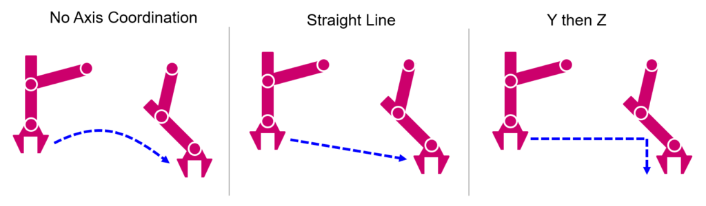
Each of the servos in the arm, will have different target angles and they will reach their targets at different times, which makes the robot movement very unpredictable (see illustration below). In the scenario that Servo 1 has to move 50 degrees, while Servo 2 has to move 20 degrees, if both are moving independently (one first another second) or they move at the same speed, the trajectory will be problematic and erratic.
This is a very well known problem in Robotics and it gets complex extremely fast (and with multiple axis and complex trajectories, it can be computational intensive).
A simple solution I came up with, was to coordinate the speed of the servos sot that they both reach their target angles at the same time. Below is the function I use and it is in operation in the video of my robot, so I can say it does give very good results and smooths out the trajectory.
There is an additional higher level motion, that does have the ability to perform Y first then Z and vice-verse and those still leverage this underlying servo coordination function.
void twoarm_step_coordinate(double toparm_target, double middlearm_target) {

  //Serial.println("--> two arm step Start /");

  double incr_steps0=1;
  double incr_steps1= 1;
  int inner_step_delay0 = 0;
  int inner_step_delay1 = 0;
  int outer_step_delay = 30;
  double i, j;
  int e0 = 0;
  int e1 = 0;

  //Reference to function:  servo_steps(int servo_num, int angle_target, int incr_step=10, int step_delay=50)

  //identify which of the arms has a greater delta in terms of degress to move
  double delta0 = abs(angle_current[0] - toparm_target);
  double delta1 = abs(angle_current[1] - middlearm_target);

  //coordinate the speed of the two access through the incremental steps, so they can move smoothly in the x/y plane
  //   (this avoids one arm finishing its movements first, and generating huge variagtionsin the real x/y position of the endpoint)
  if (delta0!=0 && delta1!=0) {
    if (delta0 >= delta1) {
      incr_steps0 = (delta0 / delta1)*incr_steps1;
      //slow down motion as steps increase (just in case big jump in steps)
      inner_step_delay0=(delta0/delta1)*0.5;
      //reduce the outer step
      outer_step_delay=outer_step_delay-inner_step_delay0;
    } else {
      incr_steps1 = (delta1 / delta0)*incr_steps0;
      //slow down motion as steps increase (just in case big jump in steps)
      inner_step_delay1=(delta1/delta0)*0.5;
      //reduce the outer step
      outer_step_delay=outer_step_delay-inner_step_delay1;
    }
  }
  //set to zero if negative value on outer delay
  if (outer_step_delay<0) {
    outer_step_delay=0;
  }

  //identify the direction of steps
  if (angle_current[0] > toparm_target) {
    i = -incr_steps0;
  } else {
    i = incr_steps0;
  }
  if (angle_current[1] > middlearm_target) {
    j = -incr_steps1;
  } else {
    j = incr_steps1;
  }

  // user the servo step functions, doing inter-twined steps until the gaps are reached.
  // we send a delay of 0 to the servo step function, given we'll control the delay in this outer loop.
  while (1) {
    // top arm moves
    if (abs(angle_current[0] - toparm_target) > incr_steps0) {
      servo_steps(0, angle_current[0] + i, incr_steps0, inner_step_delay0);
    } else {
      servo_steps(0, toparm_target, incr_steps0, inner_step_delay0);
      e0 = 1;
    }
    // middle arm moves
    if (abs(angle_current[1] - middlearm_target) > incr_steps1) {
      servo_steps(1, angle_current[1] + j, incr_steps1, inner_step_delay1);
    } else {
      servo_steps(1, middlearm_target, incr_steps1, inner_step_delay1);
      e1 = 1;
    }
    delay(outer_step_delay);
    if ((e0 + e1) >= 2) break;

  }

  //Serial.println("--> two arm step End /");

}
In step five, we place the top arm right on the Z axis (bubble 1) and by performing a rotation by alpha+beta (bubble 3),
* Shouldn’t this read as (bubble 2)
2) By finding H, you using the pythagorean theorem (a2 + b2 = c2), why are you multiplying by (1/2) when you finding H ?
Regards
Kerwin
Hello, I find a mistake from your formula. Step5: the servo 2’s angle is not like that. That should be θ = arctan [ (ym – y3) / (z3 – zm) ]. I don’t judge whether the angle is positive or negative. But obviously, The calculation of your formula is surplus angle.
Regards
Raymond Meng
it is a great work. especially thanks very-very much for step by step very detail manual!!!!
Thanks for sharing the research.
In our case, “Carmera” function calculate and gives the informations with Depth and X/Y Pixel.
We try to use the position control(cm) of robot by using that X/Y Pixel vlaues
Depends on the distance with the target object, the pixcel data changing.
So, it is not easy to use X/Y pixel data as pysical unit (ex, cm or mm)
Your research is that the depth information fixed on the desk and therefore it’s not change X/Y pixel of the object. As I fast review your code, do you have considering the double check for improving control?
(The double check means that robot control use the information with a depth and XY pixel during robot moving as over twice)